

一种阻抗测量电路的设计
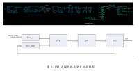
摘要:设计采用阻抗测量芯片AD5933,以低功耗高性能处理器LUMINARY615作为控制器,利用比例测量,DFT数字解调,软件校准和补偿等技术实现了对阻抗的高精度测量。通过外接模拟开关并通过软件设计实现了量程自动转换,并能在不同频率下进行测量,能通过良好的人机界面来实时控制与显示。测试结果表明,在一定范围内测量阻抗的幅值相对误差小于1%,实现了较高精度的阻抗测量。
关键词: 阻抗测量 ; AD5933 ;自动量程转换 ;Luminay615
Design of an impedance measuring circuit
Abstract: This design uses impedance measurement chip AD5933, with low power and high performance processor LUMINARY615 as controller, using ratio measurements, DFT digital demodulation, software calibration and compensation technology to achieve the high precision measurement of impedance. Through the external analog switch and the software design to achieve a range of automatic conversion, and can be measured at different frequencies, can be controlled through a good man-machine interface and display. The test results show that the relative error of the measured impedance is less than 1% in a certain range, and the impedance measurement is realized.
Keywords: impedance measurement; AD5933; automatic range conversion; Luminay615
目 录
1. 系统设计 3
1.1设计要求 3
1.2方案论证与比较 3
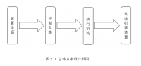
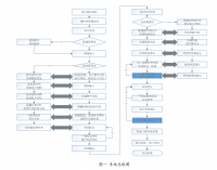
1.3 系统方案 5
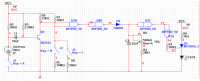
2. 硬件电路设计 6
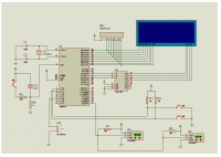
2.1 处理器电路设计 6
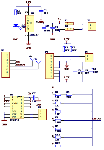
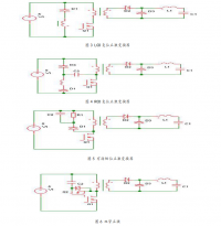
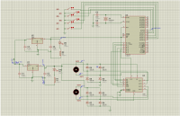
2.2 阻抗测量电路设计 6
2.2.1 AD5933 芯片简介 6
2.2.2 AD5933工作原理 7
2.2.4 测量电路 9
3. 软件设计 10
3.1编程环境介绍 10
3.2 I2C通行协议简介 10
3.3 软件设计 11
4. 系统测试 13
4.1测试仪器 13
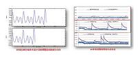
4.2测试方法与结果 13
4.3 误差分析 14
5. 结论 15
6.参考文献 15
附录一 元器件清单 16
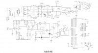
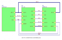
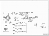
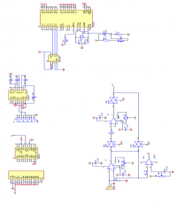
附录二 原理图以及PCB图 16
附录三 程序清单 23
参考文献
[1]http://www.analog.bysj1.com/static/imported-files/data_sheets/AD5933.pdf
[2] 崔传金,郭志强,赵楠,左月明.用AD5933实现电导率测量的研究, 机电工技术,2008.37(4)
[3] 高吉祥.全国大学生电子设计竞赛培训系列教程[M].北京:电子工业出版社,2007.12
http://www.bysj1.com/ http://www.bysj1.com/html/5275.html http://www.bysj1.com