

基于UG的圆钻模零件三维造型及设计
摘要:文主要介绍圆钻模零件造型及结构设计。通过AutoCAD和UG制图软件完成对本圆钻模零件造型及结构设计。设计的重点是选定圆钻模零件造型及结构,通过AutoCAD对圆钻模零件的二维平面图进行绘制设计,了解圆钻模零件各个零件的机械要求,其中包括孔的公差,各零件与夹具体的形位公差以及各零件的粗糙度。平面图绘制设计好后需用UG对各个零件进行三维造型,然后将各零件进行装配。因此本文要全面的多方位的介绍AutoCAD和UG制图软件,并详细的记录AutoCAD和UG制图软件对各个零件的设计与绘制的过程。还要展示UG三维实体设计软件对各个零件进行的装配过程。
圆钻模零件造型与设计是本设计的重中之重,而圆钻模零件造型的虚拟建模装配又是另一重点。
关键词:圆钻模;AutoCAD;UG;装配。
Round diamond shape and structure design of mould parts
Abstract:Article mainly introduces the round shape and structure design of drilling jig parts. By AutoCAD and UG graphics software to complete this round diamond shape and structure design of mould parts. Design is the focus of the selected round parts shape and structure, the diamond by AutoCAD 2 d floor plan of round diamond die parts drawing design, understand the round diamond mechanical requirements of the various parts of the mold parts, including the tolerance of hole, the parts with clamp concrete shape tolerance and roughness of the parts. Built in the layout drawing with UG three-dimensional modelling of the parts, then the parts are assembled. So this article will comprehensively the all-round introduction of AutoCAD and UG drawing software, and the detailed record of AutoCAD and UG graphics software for the various parts of the process of design and drawing. Also show the UG 3 d entity design software for the assembly process of the parts.
Round diamond die parts modeling and design is the focus of this design, the round shape modeling of virtual assembly jig parts is another focus.
Keywords:Round drill jig; AutoCAD; UG; Assembly.
目 录
第一章 绪论 2
1.1圆钻模的组成部分 2
1.2圆钻模工作原理 2
第二章 软件介绍 3
2.1 Autocad软件的介绍 3
2.2 UG软件的介绍 4
第三章 圆钻模装配图的识读 5
3.1机械图样的识读 5
3.2读圆钻模装配图 5
第四章 圆钻模零件图的拆画 8
4.1 拆画特制螺母 8
4.2 拆画底座 11
4.3 拆画钻模板 14
4.4 钻套 16
4.5 拆画轴 18
4.6 拆装开口垫圈 22
4.7 拆画衬套 26
第五章 圆钻模三维图的绘制 29
5.1 底座三维图 29
5.2 钻模板三维图 34
5.3 钻套三维图 36
5.4 轴三维图 37
5.5 开口垫圈三维图 40
5.6 衬套三维图 42
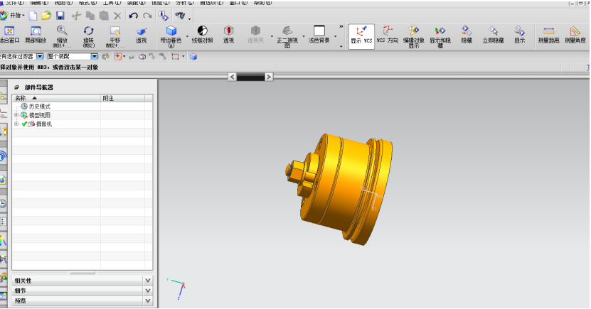
5.7 特制螺母三维图 44
致 谢 45
参 考 文 献 46
附录 47
附件一:圆钻模零件的装配图 47
附件二:底座 48
附件三:钻模板 49
附件四:钻套 50
附件五:轴 51
附件六:开口垫圈 52
附件七:特质螺母 53
附件八:衬套 54
附件九:螺母M10 55
附件十:工件 56
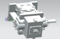
附件十一:圆钻模零件三维造型结构图 57
附件十二:底座三维造型图 58
附件十三:钻模板三维造型图 59
附件十四:钻套三维造型图 60
附件十五:轴三维造型图 61
附件十六:开口垫圈三维造型图 62
附件十七:特制螺母三维造型图 63
附件十八:衬套三维造型图 64
附件十九:螺母M10三维造型图 65
附件二十:圆钻模的三维造型爆炸图 66
第一章 绪论
1.1圆钻模的组成部分
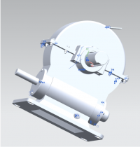
圆钻模是一种钻夹具,加工时把工件放在底座上,装上钻模板,钻模板上装有三个等分的钻套件和件套圈,钻模板通过件圆锥销定位后,再装上件开口垫圈,最后用件特制螺母与件螺母同时旋紧,装夹完毕;然后在钻床工作台上手工移动钻模调整钻套与钻头的相对位置就能钻削工件了。
1.2圆钻模工作原理
把工件放在底座上,工件实现了部分定位;装上钻模板,通过圆柱销实现了钻模板定位,工件的定位就完成了;由上下螺母实现了工件夹紧;快卸垫圈使装夹快捷方便。
参 考 文 献
1、 基斌,晏群,机械制图{M},北京:机械工业,2008.1。
2、王韦伟Autocad 2007实用教程{M},西安:西安电子科技大学出版社,2008,2.
3、董继明,机械制图与CAD{M},北京理工大学出版社,2008,8.