


采用热传感器的水阀控制系统
摘要:在日常生活中都会需要用到热水,但往往水的温度不能达到我们自己想要的温度,因此水温的控制就相当的重要。本设计以AT89C51单片机为核心,周围包含温度采集电路、LCD1602液晶显示电路、键盘输入电路、报警电路和继电器连接水泵的电路,本设计电路还需要一个将220V的电源转换成正负5V的电源电路,为单片机和其他各部分之路提供一个可以使用的电压。当温度传感器采集到水的温度后,传送给单片机,并且在LCD1602液晶显示屏上显示当前的温度。当水的温度达到我们所需要的温度时,水阀们打开,水流出来。该系统可以实时的采集到水的温度,并且当水的温度超过一定值时,报警电路中的蜂鸣器就会响来提示我们水温过高。具体设计原理以及过程在下面章节中详细说明。
关键字:单片机AT89C51:LCD1602:DS18B20
The water valve control system of heat sensor
Abstract:In life we need to use hot water bath, but the water temperature is not up to our own temperature, so temperature control is very important. The design AT89C51 microcontroller as the core, including temperature acquisition circuit, LCD1602 peripheral circuit of liquid crystal display circuit, keyboard input circuit, alarm circuit and the relay is connected with the water pump, the design of the circuit also requires a 220V power into the power supply circuit of positive and negative 5V, provide a can be used for other parts of SCM and voltage the road. When the temperature sensor to the temperature of the water, and transmitted to the microcontroller, display the current temperature in the LCD1602 liquid crystal display. When the water temperature reaches the needed temperature, water valves are opened, the water flow out. Real time acquisition to the water temperature of the system, and when the water temperature exceeds a certain value, the buzzer will sound the alarm circuit to suggest that the water temperature is too high. The design principle and process in detail in the following sections.
Keyword:Single chip microcomputer AT89C51,LCD1602,DS18B20
目录
1 引言 1
1.1 热传感器的水阀控制系统研究的背景和意义 1
1.2 热传感器的水阀控制系统的内容 1
2 总体方案设计 2
2.1 功能的实现以及设计思路 2
2.1.1 功能的实现 2
2.1.2 设计思路 2
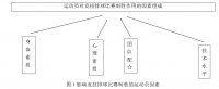
2.2 系统的总体方框图 3
2.3 各个电路的方案论证 3
2.3.1 电源电路 3
2.3.2 温度采集电路 4
2.3.3 显示电路 5
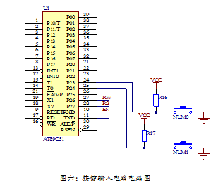
2.3.4 按键输入电路 7
2.3.5 报警电路 7
3 硬件电路设计 8
3.1 AT89C51单片机 8
3.1.1 管脚说明 8
3.1.2 单片最小系统电路 9
3.1.3 单片机电路功能介绍 9
3.2 电源电路 10
3.2.1 电源电路的原理图 10
3.2.2 电源电路的功能介绍 10
3.3 温度采集电路 11
3.3.1 温度采集电路原理图 11
3.3.2 温度采集电路功能介绍 11
3.3.3 温度传感器的特性 11
3.3.4 温度传感器的工作过程 12
3.4 显示电路 12
3.4.1 显示电路原理图 12
3.4.2 显示电路的功能介绍 12
3.4.3 显示电路的工作过程 14
3.5 按键输入电路 15
3.5.1 按键输入电路原理图 15
3.6 报警电路 15
3.6.1 报警电路原理图 15
3.6.2 报警电路功能介绍 16
3.7 阀门电路 16
3.7.1 阀门电路原理图 16
3.7.2 阀门电路功能介绍 17
4 软件电路设计 17
4.1 主程序 17
4.1.1 流程图 17
4.1.2 主程序代码 18
4.2 温度采集系统流程图 19
4.2.1 流程图 19
4.2.2 程序 20
4.3 液晶显示 20
4.3.1 流程图 20
4.3.2程序 21
4.4 按键输入电路 22
4.4.1 流程图 22
4.4.2 程序 23
4.5 报警电路和阀门电路 24
4.5.1 流程图 24
4.5.2 程序 25
5 调试 26
5.1 检查硬件连接 26
5.2 检查软件系统 26
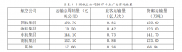
6 元器件技术指标参数 27
7 毕业设计总结 28
参考文献 30
附录一 ...........................................................................................................................29
附录二 ...............................................................................................................................30
参考文献
[1] 常慧玲.传感器与自动检测[M]北京:电子工业出版社,2012
[2]李岁劳.杨鹏翔.朱新颖.基于C8051单片机的多路温度无线遥控系统[J].计测技术,2008(7):80-83.
[3]焦敏.基于DSB18B20的测温系统设计[J].中国通信,2009(11):33-36.
[4]王静霞.单片机应用技术(C语言版)[M]北京:电子工业出版社,2013
[5] 任为民.电子技术基础课程设计[M]. 中央广播电视大学出版社.1997年5月第1版
[6] 张毅坤.单片微型计算机原理及应用[M]. 西安电子科技大学出版社. 1998.9第1版
[7]刘文,杨欣,张铠麟.基于AT89C51单片机的指脉检测系统的研究[J].医疗装备.2005
[8] 朱月秀.单片机原理与应用[M].科学出版社.2004.2
[9]王静霞.单片机应用技术(C语言版)[M]北京:电子工业出版社,2013
[10]胡宴如.模拟电子技术(第三版)[M]北京:高等教育出版社,2013
http://www.bysj1.com/ http://www.bysj1.com/html/2478.html
http://www.bysj1.com/html/1568.html