


四通道故障报警仪的设计
摘要:本文设计一个四通道故障报警仪,能同时接收四路电压信号,对各种参数实时采集和故障诊断报警,对工业生产过程中的现场仪器以及设备因发生故障而产生的超出正常电压范围的故障电压信号进行超限报警,能同时判别发生故障的通道号并送显示器显示,能够根据故障发生与否控制故障报警指示灯或无故障信号指示灯点亮,并控制蜂鸣器在故障时响起报警。
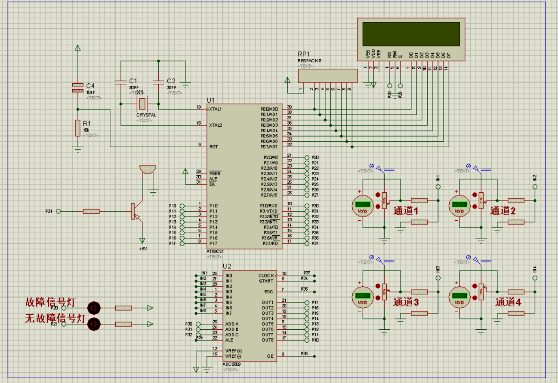
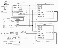
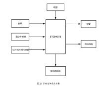
四通道输入的电压(通过调节滑动变阻器来产生为0~10V的被测直流电压)信号通过AD0809转换为数字信号后通过单片机AT89C51来采集处理,然后液晶显示器通过接受单片机AT89C51发出的数字信号显示各个通道号以及电压值。当个通道电压均正常,液晶显示器也会显示四个通道的电压值,绿灯(无故障报警灯)亮,红灯(故障报警灯)熄灭,蜂鸣器无反应。当有通道不在其电压范围内,液晶显示器也会显示四个通道的电压值,通过观看电压值可以知道那个通道发生故障,红灯(故障报警灯)亮,绿灯(无故障报警灯)亮熄灭,蜂鸣器发出警报声。这样就组成了基于单片机的四通道电压超限报警仪系统,可广泛应用在各个领域之中。
关键词:四路电压;数据采集;单片机;AD转换器
Design of Four Channel Fault Alarm
Abstract: This paper designs a f,our-channel fault alarm, which can receive four voltage signals simultaneously, real-time acquisition and fault diagnosis of various parameters of the alarm, the industrial production process of the equipment and equipment due to failure caused by the normal voltage range Of the fault voltage signal to exceed the alarm, can also identify the failure of the channel number and Send display to display according to the occurrence of failure or not to control the fault alarm light or no fault signal light, and control the buzzer in the event of failure Sounded an alarm.
Four-channel input voltage (by adjusting the sliding rheostat to produce 0 ~ 10V measured DC voltage) signal through the AD0809 converted to digital signal through the microcontroller AT89C51 to collect processing, and then through the LCD microcontroller AT89C51 digital signal display by the various Channel number and voltage value. When the channel voltage is normal, the LCD display will display the voltage value of the four channels, green (no fault warning light) light, red light (fault alarm light) goes out, the buzzer no response. When the channel is not within its voltage range, the LCD will also display the voltage value of the four channels, through the watch voltage value can know that channel failure, red light (fault alarm light) light, green (no fault alarm light) , The buzzer sounds an alarm. This will be based on the single-chip four-channel voltage overrun alarm system can be widely used in various fields.
Key words: four-way voltage, data acquisition;,single-chip, AD converter
目录
目录 II
第1章绪论 1
1.1 课题研究的背景 1
1.2课题研究的现状 1
1.3 设计的主要内容 2
第2章 总体设计方案确定 2
2.1 设计要求 4
2.2 设计方案 5
2.3原理框图 5
第3章系统硬件设计与实现 6
3.1硬件系统的概括 6
3.2A/D转换模块 6
3.2.1.1 ADC0809内部功能 7
3.2.1.2 ADC0809引脚介绍 8
3.3四路电压信号输入模块 8
3.4微型处理器模块 10
3.4.1AT89C51单片机 10
3.4.2复位电路 13
3.4.3 振荡电路 13
3.4.4微处理器模块电路图 14
3.5故障报警模块 14
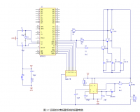
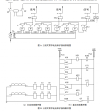
3.5.1 故障通道信号显示报警电路 15
3.5.2 光报警模块电路 19
3.5.3 声报警模块电路 20
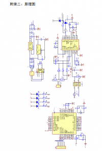
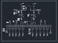
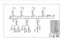
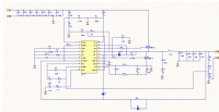
3.6系统硬件原理图 20
第四章系统软件设计与实现 21
4.1流程图及程序的设计说明 21
4.1.1主流程序图 22
4.1.2 子流程序图 23
4.2 程序设计 24
4.2.1创建工程 24
4.2.2 编写程序 28
第5章系统仿真调试与运行 30
5.1 调试内容 30
5.1.1软件调试 30
5.1.2软硬件联合调试 31
5.2 运行过程及结果 32
5.2.1系统运行状况 32
5.2.2系统调试,运行结果分析 37
总结 38
参考文献 39
致谢 40
附录A 41
附录B 42
参考文献
[1]马明建.数据采集与处理技术.西安:西安交通大学出版社,2005年
[2]徐爱卿,孙涵芳,盛焕鸣.单片微型计算机应用和开发系统.北京航空航天大学出版社,1992年
[3]吴黎明.单片机原理及应用技术.北京:科学出版社,2005年
[4] 邬宽明.单片机外围器件实用手册 数据传输接口器件分册.北京航空航天大学出版社,1998年
[5] 何立民,余永权,李小青,陈林康. 单片机应用系统的功率接口.北京航空航天大学出版社,1992年
[6] 张毅刚,彭喜元,孟升卫,刘兆庆. MCS-51单片机实用子程序设计(第二版). 哈尔滨工业大学出版社,2003年
[7] 胡汉才.单片机原理及接口5技术(第2版).清华大学出版社,2004年
[8] 刘勇. 《数字电路》. 电子工业出版社,2004
[9] 王法能.《单片机原理及应用》(简明修订版).科学出版社出版发行, 2001
[10] 赵伟军.PROTEL 99 SE 教程.人民邮电出版社,2004
[11] 黄强.模拟电子技术.科学出版社,2003
[12] 王鹏飞.基于单片机数据采集及传输系统的研究重庆职业技术学院学报2008
[13] 余永权. ATMEL89系列(MCS-51兼容)FLASH单片机原理及应用. 电子工业出版社, 1997
[14]李念强.数据采集技术与系统设计.机械工业出版社,2006
[15] 沈兰荪.数据采集技术.中国科学技术大学出版社,2001
[16] 周林,殷侠.数据采集与分析技术.西安电子科技大学出版社,2000
http://www.bysj1.com/html/6464.html
http://www.bysj1.com/html/6462.html