


机用虎钳零件造型及结构设计
摘 要:机用虎钳,机用虎钳又叫机用平口钳,是配合机床加工时用于夹紧加工工件的一种机床附件。机用虎钳的工作原理:用扳手转动丝杠,通过丝杠螺母带动活动钳身移动,形成对工件的加紧与松开。机用平口钳装配结构是将可拆卸的螺纹连接和销连接的铸铁合体;活动钳身的直线运动是由螺旋运动转变的;工作表面是螺旋副、导轨副及间隙配合的轴和孔的摩擦面。其设计结构简练紧凑,夹紧力度强,易于操作使用。内螺母一般采用较强的金属材料材料,使夹持力保持更大,一般都会带有底盘,底盘带有180°刻度线可以360°平面旋转。
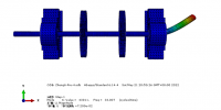
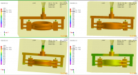
本次课题的内容是设计一磨床机用虎钳,使用计算机辅助设计软件(NX7.0)完成整体机构建模与装配,加载伺服电机进行运动仿真分析,得出结论。工件的装夹方法有两种:一种是工件直接装夹在机床的工作台或花盘上;另一种是工件装夹在夹具上,虎钳属于第二种装夹方法。根据我们所学的《机床夹具》《机械设计基础》研究了机用虎钳的组成构造,发现虎钳具有简练紧凑,夹紧力度强,增利特性好,易于操作使用等特点。一般很适合中型铣床、钻床、以及平面磨床等机械设备使用。
关键词:机用虎钳 丝杠 加紧与松开 机械设备
THE design with the vice parts modeling and construction machine
Abstract: The machine vice, the machine vice is also called machine vise, is used for a machine tool accessory clamping workpiece with machining. Machine working principle of vice: using a wrench to rotate the screw, drive the movable clamp body moving through the screw nut, the formation of the workpiece stepping up and release. Machine vise assembly structure is the thread connecting the removable and pin iron fit connection; linear motor activity of the pliers body is change from the spiral movement; the work surface is a screw pair, friction surface of guide rail pair and a clearance fit with the shaft and hole. The design of concise and compact structure, strong clamping force, easy to operate. Internal nuts generally used metal materials with strong clamping force, to maintain larger, usually with the chassis, the chassis is provided with a 180 DEG scale line can be 360 degrees plane rotation.
The subject matter is vice design of grinding machine, using the software of computer aided design (NX7.0) modeling and assembly to complete the overall mechanism motion simulation analysis of loaded servo motor, the conclusion. Workpiece clamping method has two kinds: one kind is the workpiece clamp on the machine table or disk; the other is the workpiece is clamped in a vise fixture, belongs to the second clamping method. According to what we have learned "fixture" "machine design foundation" of the machine vice composition structure, found that vice has concise and compact, strong clamping force, increase profit performance is good, easy to use and so on. In general it is suitable for medium-sized milling machine, drilling machine, grinding machine and other mechanical equipment use and plane.
Keywords: The machine vice: Screw: . Step up and release: Mechanical equipment
.
目录
第一章 绪论 1
1.1机用虎钳的造型设计方案 1
1.2 机用虎钳的简单介绍 1
1.3 Autocad软件的介绍 2
1.4 UG软件的介绍 3
第二章 机用虎钳装配图的识读 4
2.1机械图样的识读 4
2.2 读机用虎钳装配图 4
第三章 机用虎钳零件图的拆画 6
3.1 拆画钳座 6
3.2 拆画活动钳口 10
3.3 拆画方块螺母 14
第四章 机用虎钳螺杆、螺母三维图的绘制 17
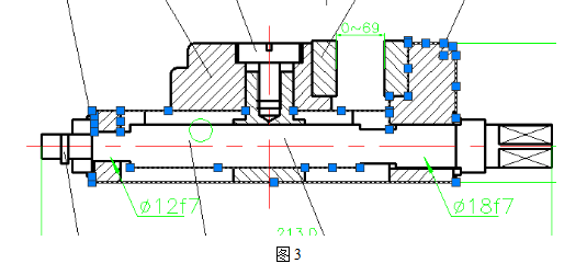
4.1螺杆的三维图 17
第五章 机用虎钳的装配 20
5.1首先按照装配线开始装配 20
5.2 活动扣钱的装配 20
5.3对螺杆和螺母进行装配 21
5.4对活动钳口上的螺钉进行装配 22
5.5对护口板进行装配 23
5.6对禁锢螺钉进行装配 23
5.7 机用虎钳的总装图 24
5.8 机用虎钳的爆炸图 25
结束语 25
致谢 26
参 考 文 献 27
附录一 28
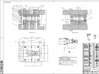
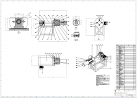
附件1.1机用虎钳装配图 28
附件1.2 钳座零件图 29
附件1.3 活动钳口零件图 29
附件1.4 螺杆零件图 30
附件1.5 方块螺母零件图 31
附件1.6 护口板零件图 33
附件1.7 螺钉零件图 34
附件1.8 垫圈零件图 35
附录二 36
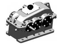
附件2.1 机用虎钳整体装配的三维图 36
附件2.2 钳座的三维图 37
附件2.3 活动口钳的三维图 38
附件2.4 方块螺母的三维图 39
附件2.5 螺杆的三维图 40
附件2.6 护口板的三维图 41
附件2.7 螺钉的三维图 42
附件2.8 螺帽的三维图 43
附件2.9 螺钉组件的三维图 44
附件2.10 垫圈的三维图 45
参 考 文 献
[1]濮良贵主编.机械设计.北京:高等教育出版社,1996.5
[2]基斌,晏群,机械制图{M},北京:机械工业,2008.1。
[3] 王韦伟Autocad 2007实用教程{M},西安:西安电子科技大学出版社,2008,2
[4]董继明,机械制图与CAD{M},北京理工大学出版社,2008,8.
[5]杨月英,张琳.中文版AutoCAD2008机械绘图[M],机械出版社,2008.
[6]刘小年,杨月英.机械制图{M},高等教育出版社,2007.
[7]张琳,杨月英机械制图{M},中国建材出版社,2008.
[8丁锋,UG NX9.0机械设计教程,北京:机械工业出版社2014]
http://www.bysj1.com/ http://www.bysj1.com/html/3268.html
http://www.bysj1.com/html/4368.html