


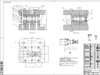
齿轮油泵零件造型及结构设计
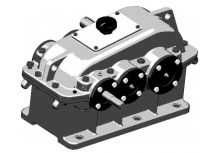
摘???要:齿轮油泵是通过一对参数和结构相同的渐开线齿轮的相互滚动啮合,将油箱内的低压油升至能做功的高压油的重要部件。是把发动机的机械能转换成液压能的动力装置。齿轮油泵由于其结构简单、制造容易、成本低,因此在国内是应用相当广泛的能用机械产品,而以外啮合泵应用最广。本分析报告中主要对油泵的齿轮、轴承、后盖、泵体进行分析,经过对零件的分析、测量和讨论,画出零件手绘图,;再经过查阅和分析有关参考书、手册、图表等技术资料,作出以下零件的功能、材料、尺寸、受CJK0615系列经济型数控车床进给伺服系统设计
摘要 :数控机床在中国从产品范围、技术水平、质量和生产取得了很大的发展,也取得了重大突破领域的一些关键技术。但我国从80年代开始开始,先天不足,在项目开发上的高端机床落后于外国主流水平,现在还在追求发展的阶段。又由于目前我国资金短缺,行业规模较小的特点,规模较小的基金迅速改变落后的生产机械行业已成为一个必须的任务,和有效的方法来完成这一任务是经济型数控机床的推广应用。
经济型数控车床具有优越的价格,价格低,并具有更好的准确性和早期满足企业发展的需要,受到企业的青睐和私人。为我们的国家或经济欠发达,经济、合理、经济的数控车床符合中国国情。
伺服给水系统作为数控机床的重要组成部分,它是移动部件的位置和速度作为自动控制系统控制量,决定了工件的加工精度。
关键词:经济型;数控机床;进给
CJK0615 series economical nc lathe feed servo system design
Abstract:NC machine tool in China from both the product variety, technical level, quality and yield have achieved great development, A major breakthrough has been made on some key technology. But our country from twentieth Century 80 time just started,be congenitally deficient.Has been in the high-end machine tool project development lags behind theforeign mainstream standards, now still pursue development stage.And because our country at present the shortage of funds, the features of industrial scale is smaller, with a smaller funds quickly change the backwardproduction features of mechanical industry has become a must task, the effective ways to realize this task is the popularization and application ofeconomic NC machine tool.
Economic type CNC lathe has a superior cost-effective, low price, and has a high accuracy, to meet the needs of the beginning of the development of enterprises, by enterprise and private favor.For the Chinese economy is still not very developed, the economic type CNC lathe economic and reasonable, to meet the conditions of our country.
Servo feed system as an important part of the NC machine tool, it is based onthe moving parts of the position and speed of the automatic control system forthe control quantity, determines the machining accuracy of workpiece.
Keywords: Economical, CNC Machine tool , Feed
目录
摘要......................................................... 3
Abstract..................................................... 4
第一章 绪论.................................................. 8
1.1 经济型数控机床的概念........................................ 8
1.1.2 数控机床的产生与发展 ................................. 9
1.1.3 数控机床的特点及应用.................................. 9
1.1.4 数控车床的组成........................................ 10
1.1.5 数控车床的控制........................................ 10
1.2 数控机床的进给伺服系统...................................... 11
1.2.1 进给伺服系统的概念.................................... 11
1.2.2 机床对伺服系统的要求.................................. 12
1.2.3 进给伺服控制的类型.................................... 13
1.2.4 各类进给伺服的组成.................................... 14
第二章 数控车床进给系统的改进................................ 15
2.1 机械执行部件................................................ 15
2.1.1 步进电动机............................................ 16
2.1.2 交流同步伺服电动机.................................... 16
2.2 传动机构.................................................... 17
2.2.1 联轴器................................................ 18
2.2.2 减速机构.............................................. 19
2.2.3 滚珠丝杠螺母副机构.................................... 20
2.3 位置检测装置................................................ 27
2.3.1 位置检测装置的概述.................................... 27
2.3.2 位置检测装置的分类.................................... 27
第三章 机械部分的计算....................................... 28
3.1 CJK0614 基本参数........................................... 28
3.2 滚珠丝杠副的设计计算....................................... 29
3.2.1 效率计算.............................................. 29
3.2.2 刚度验算.............................................. 29
3.3 电机的设计与选用........................................... 30
3.3.1 步进电机............................................. 30
3.3.2 交流伺服电机......................................... 30
第四章 进给系统部件的安装与调试............................ 31
4.1 安装准备前工作............................................ 32
4.2 机械部分安装的工序及调试.................................. 32
第五章 进给系统故障的典例.................................. 33
5.1 滚珠丝杠螺母副常见的故障与排除方法........................ 33
5.2 伺服进给系统常见故障形式 ................................. 34
第六章 小结并致谢........................................ 35
参考文献.................................................... 37
附录........................................................ 38
力和生产方式的分析,从国外先进技术和经验中吸取长处、积极探索,在设计中培养自己分析问题、解决问题的能力,力争独立思考、勇于创新,为今后的工作打下一个良好的基础。
齿轮油泵的发展历史:公元前100年左右就有了类似齿轮油泵的工业用具,据说是古希腊工匠克特西比乌斯发明的灭火泵是一种最原始的活塞泵,已具备典型活塞泵的主要元件,但活塞泵只是在出现了蒸汽机之后才得到迅速发展。
1840~1850年,美国沃辛顿发明泵缸和蒸汽缸对置的,蒸汽直接作用的活塞泵,标志着现代活塞泵的形成。然而随着需水量的剧增,从20世纪20年代起,低速的、流量受到很大限制的活塞泵逐渐被高速的离心泵和回转泵所代替.国内的第一台齿轮泵生产在原泊头市齿轮油泵总厂,在2005年已正式改名为河北恒盛泵业股份有限公司。早在1588年就有了关于四叶片滑片泵的记载,以后陆续出现了其他各种回转泵,但直到19世纪回转泵仍存在泄漏大、磨损大和效率低等缺点。
1689年,法国物理学家帕潘发明了四叶片叶轮的蜗壳离心泵。但更接近于现代离心泵的,则是1818年在美国出现的具有径向直叶片、半开式双吸叶轮和蜗壳的所谓马萨诸塞泵。现在的离心泵已经可以现实了自吸,多吸。立式以及卧式多种用途。1851~1875年,带有导叶的多级离心泵相继被发明,使得发展高扬程离心泵成为可能。
关键词:齿轮轴承、油泵后盖、泵体、零件、分析
参考文献
王侃夫 ,数控机床控制技术与系统. -2版. -北京:机械工业出版社,2007. 121-129
张俊生 ,金属切削机床与数控机床. -北京: 机械工业出版社,2001. 151-175
蔡廷文 张冰蔚,机电系统故障分析与维护. -北京:化学工业出版社,2005. 112-114
CJK0615经济型数控车床使用说明书(机械部分).浙江金火机床有限公司. 4-8
Gear pump?parts modeling?and structure desig
Abstract: ?to?gear pump?through mutual?meshing?of a pair of?involute gearparameters and?structure of?the same,?the tank
An important component of?low pressure?in the oil?to?the high-pressure oil?canwork.?The engine?is?to?convert mechanical energy into?hydraulic energy?powerdevice.?Gear pump?because of its simple structure,?easy manufacture,?low cost,so it?is applied in China?can use a wide range of mechanical?products,?and?the most widely used?outside?gearing pump.?Analysis?of?the?main?oil pump?gears,bearings,?a back cover,?a pump body?of the?analysis report,?after analysis,?the parts of the?measurement?and discussion,?draw the parts?drawing,;?by?and analysis of relevant?reference books,?manuals,?diagrams?and other technical information,?make the following?parts of?function,?material,?size,?analysis of forceand the mode of production,?and actively explore the?strengths,?learn?fromforeign advanced technology and?experience,?to develop their ability to?analyze problems,?to solve the?problems?in the design,?and strive to?independent thinking,the courage to innovate,?to lay a good foundation?for future work.
The development history?of the gear pump:?BC?100 years or so?has?industrial appliance?similar?gear pump,?fire?pump?is said to be the?ancient Greek?craftsmeninvented by Kurt Siby Lucius?is one of?the most primitive of the?piston?pump,?has the?main components of a typical piston pump,?but after the?piston pump?is only in the?present?of the steam engine?was developed rapidly.
From 1840 to 1850,?American?Worthington invented the?pump cylinder and steam?cylinder boxer,?direct effect of the steam piston pumps,?marked the formation of modern piston pump.?However,?with the drastic increase of water demand,?from twentieth Century?since 20,?piston pump?speed,?large limit to the flow are gradually?replaced by high-speed centrifugal pumps?and?rotary pump.The domestic?first?gear pump?production of?Botou city in the original?gear pumpgeneral factory,?in 2005?has been officially?renamed?Hebei Hengsheng pumpLimited by Share Ltd.
.?As early as 1588?had a?4-vane?pump?records,?later have a?variety of other rotary pump,?but it was not until nineteenth Century that?still exist in rotary pump leakage,?wear?the shortage?and low efficiency.
In 1689,?French physicist Papin invented?4-impeller volute centrifugal pump.?But the more?close to the modern centrifugal pump,?is in 1818,?appeared in the United States?with straight radial blades,?semi - open double suction?impeller and volute?so-called Massachusetts pump.?Centrifugal pump?is?realistic?self absorption,?multi suction.?Vertical?and?horizontal?multiple purposes.?From 1851 to 1875,?multistage centrifugal pumps with guide vane?were?invented,?which make the development of?high lift centrifugal?pump?is possible.
Keywords?gear?bearing,?pump?cover,?a pump body,?parts,?analysis
.
目录
第一章 绪论 1
1.1齿轮油泵的造型设计方案......................................................... 1
1.2 齿轮油泵的简单介绍............................................................. 1
1.3 Autocad软件的介绍............................................................... 2
1.4 UG软件的介绍................................................................... 4
第二章 齿轮油泵装配图的识读 6
2.1机械图样的识读................................................................. 6
2.2 读齿轮油泵装配图............................................................... 6
第三章 齿轮油泵零件图的拆画 8
3.1 拆画泵盖....................................................................... 8
3.2 拆画齿轮...................................................................... 12
3.3 拆画泵体...................................................................... 15
3.4 拆画压盖...................................................................... 18
3.5 拆画带轮...................................................................... 21
3.6 拆画小轴...................................................................... 24
3.7 拆画齿轮轴.................................................................... 26
3.8 拆画纸垫片.................................................................... 29
第四章 齿轮油泵三维图的绘制 31
4.1 泵盖的三维图.................................................................. 31
4.2 齿轮的三维图.................................................................. 33
4.3 泵体的三维图.................................................................. 34
4.4 压盖的三维图.................................................................. 37
4.5 带轮的三维图.................................................................. 38
4.6 小轴的三维图.................................................................. 39
4.7 齿轮轴的三维图................................................................ 40
4.8 纸垫片的三维图................................................................ 42
4.9.1标准件的三维图.............................................................. 43
4.9.2 螺钉的三维图................................................................................................................................. 44
第五章 齿轮油泵的装配 46
5.1首先按照装配线开始装配........................................................ 46
5.2 齿轮轴的装配线................................................................ 46
5.3 齿轮的装配线.................................................................. 47
5.4 小轴的装配线.................................................................. 48
5.5 纸垫圈的装配线................................................................ 48
5.6 泵盖的装配线.................................................................. 49
5.7 垫圈的装配线.................................................................. 50
5.8 螺丝的装配线.................................................................. 50
5.9 销子的装配线.................................................................. 51
5.10 压盖的装配线................................................................. 52
5.11 压盖垫圈的装配线............................................................. 52
5.12 压盖螺丝的装配线............................................................. 53
5.13 平键的装配线................................................................. 54
5.14 带轮的装配线................................................................. 54
5.15 平垫圈的装配线............................................................... 55
5.16 螺母的装配线................................................................. 56
5.17 齿轮油泵的爆炸图............................................................. 57
结束语 61
致谢 62
参 考 文 献 63
附录一 64
附件1.1齿轮油泵装配图............................................................ 64
附件1.2 泵盖零件图............................................................... 64
附件1.3 泵盖的零件图.............................................................. 65
附件1.4 带轮零件图............................................................... 65
附件1.5 齿轮零件图............................................................... 66
附件1.6 齿轮轴零件图............................................................. 66
附件1.7 压盖零件图............................................................... 67
附录二 68
附件2.1齿轮油泵整体装配的三维图.................................................. 68
附件2.2 泵盖零件图............................................................... 68
附件2.3 带轮的三维图............................................................. 68
附件2.4 齿轮的三维图............................................................. 69
附件2.5 齿轮轴零件图............................................................. 70
附件2.6 压盖零件图............................................................... 70
参 考 文 献
[1]濮良贵主编.机械设计.北京:高等教育出版社,1996.5
[2]基斌,晏群,机械制图{M},北京:机械工业,2008.1。
[3] 王韦伟Autocad 2007实用教程{M},西安:西安电子科技大学出版社,2008,2
[4]董继明,机械制图与CAD{M},北京理工大学出版社,2008,8.
[5]杨月英,张琳.中文版AutoCAD2008机械绘图[M],机械出版社,2008.
[6]刘小年,杨月英.机械制图{M},高等教育出版社,2007.
[7]张琳,杨月英机械制图{M},中国建材出版社,2008.
[8]展迪优,UG NX9.0 机械设计教程{M},机械工业出版社,2014
http://www.bysj1.com/ http://www.bysj1.com/html/4268.html
http://www.bysj1.com/html/3068.html