

轴齿轮零件工艺及专用夹具设计
摘要:本次毕业设计内容主要包括了齿轮套的三维建模和零件图的绘制以及针对该型号的齿轮套
的工艺路线的设计,以及涉及使用的夹具方案的制定。通过零件图纸上的粗糙度要求及互换性测量来制定出合理的夹具使用方案。
齿轮套加工工艺工装设计是采用45号钢的锻件来进行后续的加工步骤,齿轮套的作用是承受载荷,
传递扭矩,传递力的方向,更改速度的大小,使得使用同一齿轮套的轴能够继续保持同步运动和相同的
速率。为了达到这种功效,所以齿轮套的内孔的精度要求十分高。我们处理这个齿轮套的工艺所需要
要求不算太高。齿轮套在加工时只需要保证粗基准面加工时的光滑度,位置度,精确度就
能够保证孔的准确度,位置度。
关键词:工艺方案,位置度,精准度
abstract
The graduation design mainly includes the three-dimensional modeling of the gear sleeve and the
drawing of the part drawing as well as the design of the process route for the gear sleeve of this type, as well as the formulation of the jig scheme involved in the use. Through the roughness requirements and interchangeability measurement of parts drawings, a reasonable fixture usage plan is worked out.The gear sleeve processing craft is designed to use the 45 steel forgings to carry on the following processing steps.
The function of the gear sleeve is to bear the load, transfer the torque, the direction of the transfer force, and change the speed, so that the axis of the same gear sleeve can continue to keep the synchronous movement and the same rate. In order to achieve this effect, the accuracy of the inner hole of the gear sleeve is very high. Our requirements for this gear set are not too high. When the gear sleeve is processed, it only needs to ensure the smoothness, location and accuracy of the rough datum plane, so that the accuracy and location of the hole can be ensured.
Key words: process plan, position degree, precision
目录
第一章绪论 2
1.1本课题的研究内容和意义 2
1.2 国内外的发展情况 2
1.3本课题应达到的要求 2
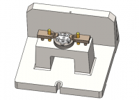
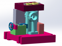
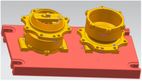
第二章造型 2
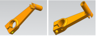
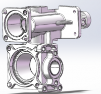
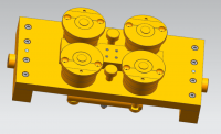
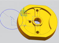
2.1 齿轮套的造型 2
第三章零件的分析 2
3.1 零件的作用 2
3.2 零件的工艺性 2
第四章工艺过程的设计 2
4.1 确定毛坯的制造形式 2
4.2基准面的确定 2
4.3工艺过程的制定 2
4.3.1工艺过程卡一 2
4.3.2 工艺过程卡二 2
4.3.3 工艺过程卡的分析和综合 2
4.4选择加工设备和工艺装备 2
4.4.1机床的选择和使用 2
4.4.2 加工刀具的选择 2
4.4.3加工时量具的选择 2
第五章机械加工余量,工序尺寸,毛坯尺寸以及工时的确定 2
5.1 机械加工余量的确定 2
5.2 毛坯的尺寸 2
5.3 切削用量及工时 2
5.3.1 工序30 2
5.3.1.1确定粗车右端端面的切削的用量 2
5.3.2 确定镗削的切削用量以及工时 2
5.3.3 工序30 2
5.3.4 工序40 2
5.3.5 工序50 2
5.3.6 工序60 2
5.3.7 工序80 2
5.3.8 工序90 2
5.3.9 工序100 2
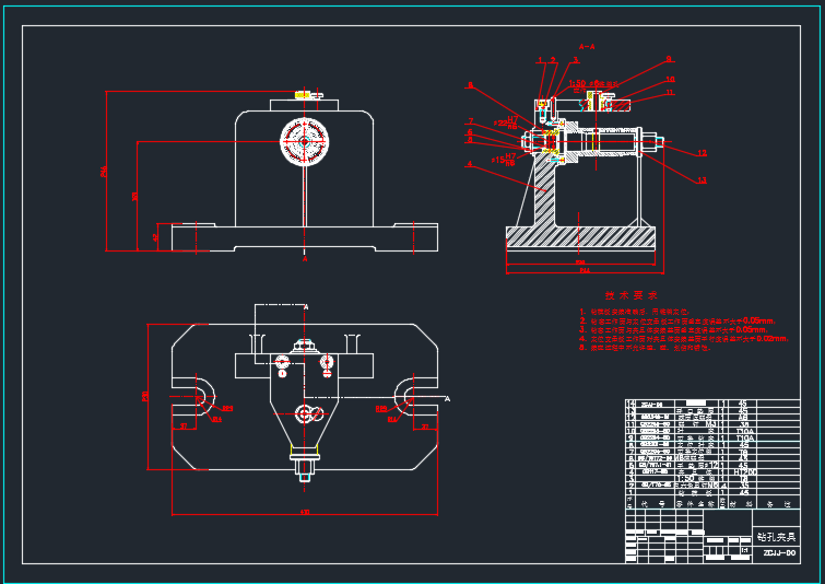
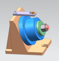
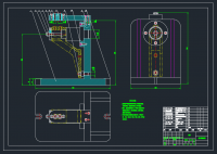
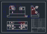
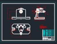
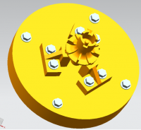
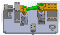
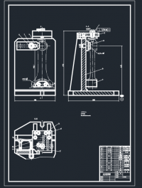
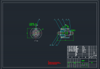
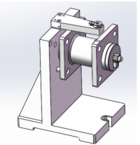
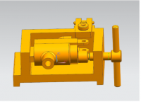
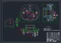
第六章Φ8.5钻孔夹具设计 2
6.1 夹具设计任务 2
6.2 夹具图示意 2
6.3基准的选择 2
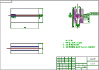
6.4夹具体的设计 2
6.5钻模版的设计 2
6.6可换式定位销的设计 2
6.7导向元件的选择 2
6.8夹紧元件 2
6.9定位误差分析 2
6.10 切削力及夹紧力的计算 2
6.11 夹具的安装方法 2
小结 2
致谢 2
参考文献 2
参考文献
(1)艾兴.肖诗纲.切削用量简明手册.机械工业出版社.2002.6.
(2)顾京.现代机床设备.化学工业出版社.2009.3.
(3)姜敏凤.董芳.机械工程材料及成型工艺.高等教育出版社 2014.7.
(4)吴慧媛.韩邦华.零件制造工艺与装备-机械制造技术.电子工业出版社 .2010.2.
(5)毛平淮.互换性与测量技术基础.机械工业出版社.2015.12.
(6)王光斗.机床夹具设计手册.上海科学技术出版.2000.
(7)赵如福.金属加工工艺人员手册.上海科学技术出版社2000.
(8)王启平.机床夹具设计.哈尔滨工业大学出版社.1996
(9)王先逵.机械制造工艺学.机械工艺出版社.2006
(10)严敏德.金属切削加工技能.机械工业出版社.2009.