


基于ANSYS轿车制动盘模态分析
摘 要
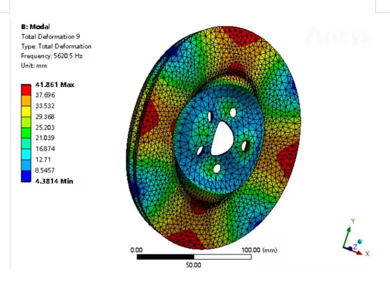
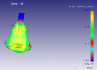
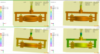
随着时间的发展,汽车功能愈加成熟,人们也愈加重视汽车安全问题。据统计,在一系列交通事故中,有接近45%的几率是制动系统失效造成的,制动系统失效往往是制动盘受到持续热冲击导致。当汽车制动时,制动盘的转速接近其固有频率时候,制动系统容易发生共振,产生噪音,危害汽车的安全。所以对制动盘进行模态与热分析很有必要。本文针对某汽车盘式制动器在制动过程产生振动与过热现象,以制动盘为研究载体,对其进行模态与热分析,最后通过改变制动盘构型来进行仿真对比分析。首先,对有限元、模态分析和热分析理论及本文所使用的ANSYS、ANSYS软件进行介绍。在此基础上,对制动盘和摩擦片进行三维建模,使用ANSYS进行网格划分得到有限元模型,参考经验公式得到热流密度、对流换热系数和制动压力的拟合曲线。其次,在ANSYS中进行模态与热分析。对制动盘和摩擦片进行模态分析,发现两者的最小固有频率远大于工作频率,且最小间隔为104.1Hz。制动盘温升模拟表明在2.40s时摩擦环上最高温度为214.05℃。通过热-结构耦合发现在1.8s时散热筋板边缘出现最大等效应力为207MPa。最后,通过对制动盘打圆孔、改变散热筋板数量、改变散热筋板厚度三种方式来进行仿真对比分析。通过打45个直径10mm圆孔,制动盘最高温度降低0.47%,起到排粉清洁的目的,质量降低3.16%,热应力增大18.84%;增加散热筋板数量为60个,制动盘最高温度降低0.3%,热应力降低9.96%,质量增加3.37%,增加相关成本;将散热筋板厚度改为14mm,制动盘热应力降低0.47%,质量降低1.16%,最高温度增加4.16%;通过减小散热筋板数量为15个、增大散热筋板厚度为14mm,制动盘与摩擦片固有频率最小间隔分别增加31.70%、43.32%,使制动更安全。
关键词:盘式制动器;虚拟样机;振动;多柔体模型
Abstract
With the development of time, the functions of automobiles have become more mature, and people are also paying more attention to car safety issues. According to statistics, nearly 45% of a series of traffic accidents are caused by the failure of the braking system, which is often caused by the continuous thermal shock of the brake disc. When a car brakes, when the speed of the brake disc approaches its natural frequency, the braking system is prone to resonance, generating noise, and endangering the safety of the car. So it is necessary to conduct modal and thermal analysis on the brake disc. This article focuses on the vibration and overheating phenomenon of a certain automotive disc brake during the braking process. The brake disc is used as the research carrier to conduct modal and thermal analysis. Finally, simulation and comparative analysis are conducted by changing the brake disc configuration. Firstly, introduce the theories of finite element analysis, modal analysis, and thermal analysis, as well as the ANSYS and ANSYS software used in this article. On this basis, a three-dimensional modeling of the brake disc and friction plate was conducted, and a finite element model was obtained by using ANSYS for mesh division. The fitting curves of heat flux density, convective heat transfer coefficient, and brake pressure were obtained by referring to empirical formulas. Secondly, conduct modal and thermal analysis in ANSYS. Modal analysis was conducted on the brake disc and friction plate, and it was found that the minimum natural frequency of the two was much greater than the operating frequency, with a minimum interval of 104.1Hz. The simulation of brake disc temperature rise shows that the highest temperature on the friction ring is 214.05 ℃ at 2.40 seconds. Through thermal structural coupling, it was found that the maximum equivalent stress at the edge of the heat dissipation rib plate was 207MPa at 1.8s. Finally, simulation and comparative analysis were conducted by drilling circular holes in the brake disc, changing the number of heat dissipation ribs, and changing the thickness of the heat dissipation ribs. By drilling 45 10mm diameter circular holes, the maximum temperature of the brake disc was reduced by 0.47%, achieving the purpose of powder removal and cleaning. The mass was reduced by 3.16%, and the thermal stress increased by 18.84%; Increase the number of heat dissipation ribs to 60, reduce the maximum temperature of the brake disc by 0.3%, reduce thermal stress by 9.96%, and increase the mass by 3.37%, increasing related costs; By changing the thickness of the heat dissipation rib plate to 14mm, the thermal stress of the brake disc is reduced by 0.47%, the mass is reduced by 1.16%, and the maximum temperature is increased by 4.16%; By reducing the number of heat dissipation ribs to 15 and increasing the thickness of heat dissipation ribs to 14mm, the minimum natural frequency interval between the brake disc and friction plate is increased by 31.70% and 43.32%, respectively, to make braking safer.
Keywords: disc brake; Virtual prototype; Vibration; Multi flexible body model
目录
1 绪论 4
1.1 制动器的分类与结构 4
1.2 汽车制动系统所存在的问题 5
1.3 制动器的研究现状 6
1.3.1 国内研究现状 7
1.3.2 国外研究现状 7
1.4 本课题的研究意义以及主要的研究内容 8
2.制动盘模态分析 9
2.1制动盘有限元模态分析 9
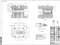
2.2有限元模型创建 10
2.3有限元模态分析结果 12
3.制动盘试验模态分析 0
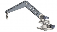
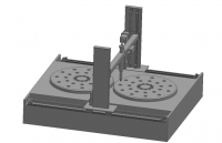
3.1模态试验设备 0
3.2模态试验过程 4
3.2.1 测点布置 4
3.2.2频率响应函数测量 5
4.制动器的刚柔耦合分析 7
4.1Ansys简介 7
4.2建立刚柔耦合模型 10
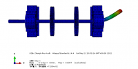
4.2.1制动盘的柔化 10
4.2.2在ADAMS中导入柔性体 18
4.3仿真与分析 25
结论 31
参考文献 32
1
绪论
1.1制动器的分类与结构
制动器是制动系统中用以产生阻碍车辆运动或运动趋势的力的部件,后一提法适用于驻车制动器。除了竞赛汽车上才装设的、通过张开活动翼板以增加空气阻力的空气动力缓速装置以外,一般制动器都是通过其中的固定元件对旋转元件施加制动力矩,使后者的旋转角速度降低,同时依靠车辆与轮面的附着作用,产生路面对车轮的制动力,以使汽车减速。凡利用固定元件与旋转元件工作表面的摩擦作用产生制动力矩的制动器,都称为摩擦制动器。
目前,各类汽车所用的的摩擦制动器可分为鼓式和盘式两大类。前者摩擦副中的旋转元件为制动鼓,其工作表面为圆柱面;后者的旋转元件则为圆盘状的制动盘,以端面为工作表面。
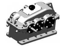
盘式制动器又叫做碟式制动器,一般是由液压控制,主要的部件有制动盘、制动钳、固定器,制动轮缸等组成。盘式制动器分为两类:浮钳盘式和定钳盘式。定钳盘式制动器的制动钳固定安装在车桥上,既不能旋转,也不能沿着制动盘轴线方向移动,因此必须在制动盘的两侧都安装制动块的促动装置,以便于将两侧的制动块分别压向制动盘。定钳盘式制动器的缺点就是:
1、制动盘的两侧各有液压缸,使制动钳的结构复杂。
2、液压缸分装于制动盘的两侧,制动液必须跨越制动盘的钳内油道或者外部的油管。
3、热负荷较大,液压缸和跨越制动盘的钳内制动管路或者是外部油管内的制动液容易气化。
4、若想兼用于驻车制动装置,则必须要添加一个机械促动的驻车制动钳。
由于上述的种种原因,定钳盘式制动装置已经很难适应现代轿车的发展趋势,也逐渐的在70年代以后让位于浮钳盘式制动器。
参考文献
[1] 蒋东鹰,管迪华.盘式制动器制动尖叫计算模型的建立[J].汽车技术,1997,(7):l~4.
[2] 蒋东鹰,管迪华.用闭环祸合模型对盘式制动器制动尖叫的研究[J].清华大学学报(自然科学版),1998,38(8):88一91.
[3] 孙振华,曾庆华,蒋东鹰,管迪华.盘式制动器制动尖叫的研究[J]. 汽车工程,1999,21(6): 326~332.
[4] 王良模,彭育辉,曾小平.浮钳盘式制动器的有限元分析[J].南京理工大学学报,2003,27(6):756-758.
[5] 宁晓斌,张文明.盘式制动器振动的多体动力学分析[J],有色金属,2004,56(4):119~121.
[6] 陈孟华.基于虚拟样机的轿车盘式制动器噪声的研究.硕士学位论文.湖北:武汉理工大学,2006.
[7] 贾杨成.虚拟样机技术在汽车制动仿真方面应用研究.硕士学位论文.安徽:合肥工业大学,2004.
[8] 安颖.制动器多柔体仿真分析.硕士学位论文.长春:吉林大学,2005.
[9] 管仁梅.大客车鼓式制动器的多柔体ADAMS建模.硕士学位论文.长春:吉林大学,2002.
[10] Fieldhouse. A Proposal to Predietthe Noise Frequeney of a Disc Brake Based on Friction Pair Interface Geometry[J]. SAE Paper 1999-01-3403,1999.
[11] CharlesL.Penninger,Riehard A.Swift Disc Brake Lining Shap OPtimizatio by Multibody Dynamic Analysis[J]. SAE Paper2004-01-0725,2004.
[12] Riehard A.Swift. A Parametric Modeling Approaeh for the Preliminary Design of Automotive Disc Brakes[J]. SAE Paper2003-01-3330,2003.
[13] Ouyang H,Nack W,Yuan Y,et al. Numerical Analysis of Auto-motive Disc Brake Squeal: a Review[J]. Int. J. Vehicle Noise and Vibration. 2005. 1(3/4) : 207 -231.
[14] Philippe Duffour.Noise Generation in Vehicle Brakes[D].Lon-don: University of Cambridge,2002.
[15] Joe Y G,Cha B G,Sim H J,et al. Analysis of Disk Brake Insta-bility Due to Friction- induced Vibration Using a Distributed Param-eter Model[J].International Journal of Automotive Technology,2008, 9( 2) :161 -171.