


Analyze Tool Wear Carbide End Mill (Ø6 2T, Ø8 3T, Ø10 4T) for Output of Force and Temperature Data using Third Wave AdvantEdge Software Simulation
利用第三波先进软件模拟分析刀具磨损硬质合金立铣刀(_62t、_83t、_104t)的力和温度数据输出
ACKNOWLEDGEMENT
First and foremost, I have to thank my research supervisors, Prof.Dr.Wanghuan Qian, vice dean also lecturer in Mechanical Engineering Wuxi Institute of Technology along Dr. Qin Feng and also Mr.Tang LiPing. Without their assistance and dedicated involvement in every step throughout the process, this paper would have never been accomplished. I would like to thank you very much for your support and understanding over these past 3 and 1 years.I would also like to show gratitude to head of Mechanical Engineering Department in Universitas Muhammadiyah Surakarta, Ir.Subroto ,M.T. His teaching style and enthusiasm for the topic made a strong impression on me and I have always carried positive memories of his classes with me. I would like also like to grateful on my friends while I spend almost a year in China. Last but not least, I would like to express my deepest love to my parents and family. Their love strengthen me through out each step of my study in China, this research project would not be possible.
Mohammad Aris Ardiyanto
CONTENTS
VALIDATION SHEET ii
FOREWORD iii
ACKNOWLEDGEMENT iv
CONTENTS v
LIST OF FIGURE vii
LIST OF TABLE viii
LIST OF GRAPH ix
ABSTRACT x
CHAPTER I INTRODUCTION 1
1.1 Background 1
1.2 Problem Statement 2
1.3 Problem Limitation 3
1.4 Objective of Research 3
1.5 Benefit 3
1.6 Preface 4
CHAPTER II LITERATURE REVIEW 5
2.1 Manufacturing Process – Milling 5
2.2 Milling Manufacturing Process 6
2.3 Machining Characteristics 7
2.4 Cutting Force and Temperature 8
2.4.1 Cutting Force 8
2.4.2 Temperature 9
2.5 Wear Resistance 9
2.6 Finite Element Model – Al 7075 11
2.7 Cutting tool of End Mill 12
2.8 Carbide End Mill 13
2.9 Modeling The Flute End Mills 14
2.10 Third Wave AdvantEdge 15
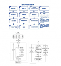
CHAPTER III METHODOLOGY PROJECT 18
3.1 Flow Chart 18
3.2 Experimental Design 19
3.2.1 Worpiece 19
3.2.2 Cutting Insert 19
3.2.3 CAD Model Preparation 20
3.3 Set up Milling Process Parameters 20
3.4 Continuous Set up Milling Process Parameters 21
3.5 Continuous Set up Machining Parameters 21
CHAPTER IV DISCUSSION ANALYZE 23
4.1 Results from Numerical Analysis 23
4.1.1 Chip Temperature Comparison 23
4.1.2 Thrust Force of Cutting Tool 25
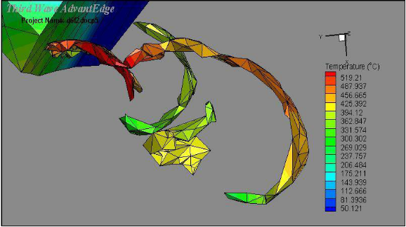
4.1.3 Temperature Field Distribution 27
4.2 Experimental Results on Cutting Tool Wear 29
CHAPTER V CONCLUSSION 30
5.1 Conclusion 30
5.2 Suggestion 31
REFERENCE
ATTACHMENT
LIST OF FIGURE
Fig.2.1 Manufacturing Relationships among Structure, Properties, Processing, and
Performance 5
Fig.2.2 Direction of Feed (a) up milling (b) down milling 7
Fig.2.3 Forces Acting on A Cutting Tool 9
Fig.2.4 3D Solid Modeling Flute End Mill on Solidwork 2015; 2 Flute, 3
Flute, 4 Flute 15
Fig.2.5 Tecplot 360 Display on Modeling End Mill with Material 16
Fig.2.6 Temperature Field Distribution in Cutting Zones 16
Fig.3.2 View of Cutting Tool End Mill 3 Flute with diameter of 8 mm 19
Fig.4.1 Chip Produced by 2T (Ø6) 23
Fig.4.2 Chip Produced by 3T (Ø8) 23
Fig.4.3 Chip Produced by 4T (Ø10). 24
LIST OF TABLE
Table 2.1 Applications for End Mill 12
Table 3.1 Chip Pocket and Teeth 20
Table 3.2 Milling Process Parameters for Analysis 20
Table 3.3 Calculation on Feed Rate Data Scheme 21
Table 3.4 Selected Machining Parameter 22
Table 4.1 Analysis on Variance of Temperature 24
Table 4.2 Variance of Thrust Force on Cutting Tools 26
Table 4.3 Peak Tool Temperature with Thrust Force Relation 28
Table 4.4 Measurement Value on Cutting Tool Wear After Experiments 29
LIST OF GRAPH
Graph 4.1 Thrust Force Result by 2T (Ø6) ................................................................. 25
Graph 4.2 Thrust Force Result by 3T (Ø8) ................................................................. 26
Graph 4.3 Thrust Force Result by 4T (Ø10) ............................................................... 26
Graph 4.7 Peak Tool Temperature by 2T (Ø6) ........................................................... 27
Graph 4.8 Peak Tool Temperature by 3T (Ø8) ........................................................... 28
Graph 4.9 Peak Tool Temperature by 4T (Ø10) ......................................................... 28
ABSTRACT
Tool wear is one of the most important topic in cutting field. Its interest is due to the influence of tool wear on surface integrity of the final parts and on tool life, and, consequently, on the production costs. The methods of process of cutting tool design has been massively used in industrial world. Based on the seeking the best performance needs of production, it is crucial to set up the proper cutters. Variations of cutting tool of 2 flute 3 flute and 4 flute End Mill Carbide Material by diameter 6mm, 8mm, 10mm, respectively are tested using FEM method using simulation of Finite Element Analysis Software which is Third Wave AdvantEdge to predict the cutting force, temperature on Aluminium AISI 1045. It also accumulated with End Mill. Comparing those for seeking the best performance production and machining parameters by manufacturing process.
Key words : Carbide End Mill 2 Flute, 3 Flute and 4 Flute for Output of Force and Temperature Data using Third Wave AdvantEdge
CHAPTER I
INTRODUCTION
1.1 Background
In the modern era, development in the fields of engineering, especially engineering technology is progressing very rapidly. The development of science is a major factor in developing of technology in the field of engineering sciences. So, in the case the speed and accuracy are the challenges that faced today. The end milling process is one of the most widely used material removal processes in industry. In general type of end mills are varied and have each purpose of every types to solve diverse problem in production.
Since the Industrial Revolution, manufacturing has been synonymous with Afactories, machine tools, production lines and economies of scale. So it is startling to think about manufacturing without tooling, assembly lines or supply chains. However, this is exactly what is happening as milling manufacture reaches individuals, small businesses and corporate departments.
There are some studies as the reference of this research. Those are researches about optimization carbide end mill with analyze and simulation. Generalized modeling of milling mechanics and Dynamics – Helical End Mill is study about predicted and measured cutting forces, surface roughness and stability lobes for ball, helical tapered ball, and bull nosed end mills are provided to illustrate the viability of the proposed generalized end mill analysis
End milling is a very common operation performed on both vertical and horizontal spindle milling machines or machining centers. For a vertical spindle end milling process, cutting a step in the workpiece. This cutter can cut on both sides and ends of the tool. If the operator was performing this operation on a block of metal, it would be the best to select a specific machine tool.
Operator would has to determine how many passes (rough and finish cuts) were needed to produce the geometry specified in the design. Due to the number of passes determines the total cutting time for the job (DeGarmo, P. et al., 2008). The tool material and cutter geometry must be designed to withstand these conditions.
And the research which using Third Wave AdvantEdge for finding optimization both in effective time reduce and also tool wear. Simulating steel machining AdvantEdge user defined and user defined yield custom material options and the path for improvement in Third Wave Software.
A classical approach has been to develop milling mechanics models that the geometric model must also include the cutting edge geometry along the flutes for analyzing the mechanics and dynamics of the milling process. Therefore, based on the description above, an amazing interest of modelling the tools which suites the most then simulation for manufacturing process in order for comparison of the best result.
1.2 Problem Statement
Finish machining is required in order to approach the perfection in manufacturing. The perfection of the cutting process may lead to the best quality of the product. Based on computer vision can be remarked in terms of speed and accuracy. The advantages this technology provides are diverse. Whereas tactile techniques characterize a linear track over the part surface, computer vision techniques allow characterizing wide areas of the part surface providing more information. Also, computer vision techniques take measures faster, since image are captured in a very short time, and they can be in-machine implemented (Alegre, E. et al., 2016). As the 2, 3, and 4 flutes are provided and modeled, as seeking the best optimum feed rate and cutting depth shown by its force and temperature, will be simulate with Third Wave AdvantEdge Software and compared with the real experiment on finding the effect on tool wear.
REFERENCE
Acchar, W., Zollfrank, C., Greil, P. 2004. Microstructure and Mechanical Properties of WC-Co Reinforced with NbC. Materials Research, Vol.7, No. 3, 445-450, 2004
Anderson, M. 2010. Integrating AdvantEdge with Knowledge and Product Development Process on Microsoft Platform. Process CIO R&D Sandvik Tooling at International Users Conference Third wave AdvantEdge
Anonymous. 2016. Introduction to Milling Tools and Their Application. Machining Cloud, Inc.
Anonymous. End Mill Training. Nachi America, Inc.
Dakin, S. and contributors. 2009. Report on Carbide: Powders and Hard Metals. National Toxicology Program, U.S Departmment of Health and Human Services, Public Health Service, Research Triangle Park, NC. 27709
Das, S.R., Nayak, R.P., Dbupal, D. Optimization of Cutting Parameters on Tool Wear and Workpiece Surface Temperature in Turning of AISI D2 Steel. International Journal of Lean Thinking Volume 3, Issue 2 (December 2012).
DeGarmo, E.P., Black, J.T., Kohser, R.A. 2008. Materials and Processes in Manufacturing Tenth Edition. United States of America: John Wiley & Sons. ISBN: 978-0470-05512-0
Engin, S. & Altintas, Y. Tandon, P. Generalized Modeling of Milling Mechanics and Dynamics: Part I - Helical End Mills. The University of British Columbia Department of Mechanical Engineering 2324 Main Mall, Vanocuver, B.C. , V6T 1Z4, Canada
Gupta, P., Dhande, S.G. 2005. Geometric Modeling of End Mills. Computer-Aided Design & Applications, Vol. 2, Nos. 1-4, 2005, pp 57-65
Hamdan A., Sarhan Ahmed, A.D., Hamdi M. Optimization Method of The Machining Parameters in High Speed Machining of Stainless Steel using Coated Carbide Tool for Best Surface Finish. International Journal Adv Manufacturing Technology, 2012; 58: 81–91.
Hu, S., Liu, F., He, Yan., Peng, B. 2010. Characteristics of Additional Load Losses of Spindle System of Machine Tools. Journal of Advanced Mechanical Design, Systems, and Manufacturing. Vol. 4, No. 7, 2010
Jung, S.C. 2010. Reduction of Development Cycle Time Using AdvantEdge FEM. Korloy Inc: Third Wave AdvantEdge International Users Conference
Kaladhar, M., Venkata, K., Subbaiah, K.V, Srinivasa Rao, CH. Optimization of Surface Roughness and Tool Flank Wear in Turning of AISI 304 Austenitic Stainless Steel with CVD Coated Tool. Journal of Engineering Science and Technology Vol. 8, No. 2 (2013) 165 - 176
Kozmin, P., Sklenicka, J., Roud, P. FEM Method in Chip Shape and Cutting Force Prediction When Drilling Difficult to Cut Materials. Journal of Manufacturing 2010 Contemporary problems of manufacturing and production management 24-26.11.2010 Poznan University of Technology, Institute of Mechanical Technology, Poland
Kim, J.H., Park, J.W., Ko, T.J. End Mill Design and Machining Via Cutting Simulation. School of Mechanical Engineering, Yeungnam University, 214-1 Daedong, Gyoungsan, Kyongbuk, 712-749, Republic of Korea. Computer-Aided Design 40 (2008) 324-333
Kumar, U., Singh, A., Kumar, R. Optimization of Machining Parameters for Tool Wear Rate and Material Removal Rate in CNC turning by Grey Relational Analysis. International Journal of Applied Engineering Research ISSN 0973-4562 Volume 11, Number 4 (2016) pp 2771-2775.
Kuttolamadom, M.A. 2012. Prediction of The Wear & Evolution of Cutting Tools in a Carbide/Ti-6Al-4V Machining Tribosystem by Volumetric Tool Wear Characterization & Modeling. A Dissertation. Clemson University, Materials Science & Engineering.
Mitrovic, A., Kovac, P., Kulundzic, N., Savkovic, B. 2016. 3D Finite Element Simulation of Milling. Journal of Production Engineering Vol.19 No.1
Nahak, S., Dewangan, S., Chattopadhyaya, S. 2015. Discussion on Wear Phenomena in Cemented Carbide. GCPF2015 Procedia Earth and Planetary Science 11 284-293
Nasri, A., Slaimi, J., Bouzid Sai, W. 3D Parametric Modelling of Milling Cutter Geometry from Analytical Analysis. International Journal of Science, Technology and Society 2016; 4(2): 35-40. ISSN: 2330-7412
Nithyanandhan, T., Manickaraj, K., Kannakumar, R. Optimization of Cutting Forces, Tool Wear and Surface Finish in Machining of AISI 304 Stainless Steel Material Using Taguchi’s Method. IJISET - International Journal of Innovative Science, Engineering & Technology, Vol. 1 Issue 4, June 2014
Noordin, M.Y., Venkatesh, V.C., Sharif, S., Elting, S., Abdullah, A. Application of Response Surface Methodology in Describing The Performance of Coated Carbide Tools when Turning AISI 1045 Steel. Journal of Materials Processing Technology 145 (2004) 46–58
Ojolo, S.J., & Ogunkomaiya, O. 2014. A Study of Effects of Machining Parameters On Tool Life. International Journal of Materials Science and Applications 2014; 3(5): 183-199. ISSN: 2327-2635
Park, K.H. 2010. Tool Wear Analysis in Various Machining Processes and Study of Minimum Quantity Lubrication (MQL). Michigan State University, Mechanical Engineering Department.
Ratnasingam, J., Ma, T.P., Ramasamy, G., Manikam, M. The Wear Characteristics of Cemented Tungsten Carbide Tools in Machining Oil Palm Empty Fruit Bunch
Particleboard. Journal of Applied Sciences 9 (18): 3397-3401, 2009. ISSN 1812-5654.