

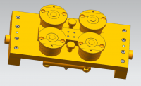
端盖夹具零件结构设计及造型
摘 要:本文主要介绍翻钻模夹具的设计。通过AutoCAD和UG制图软件完成对翻转式钻模夹具的设计。
设计的重点是选定零件翻转式钻模夹具,通过AutoCAD对翻转式钻模夹具的二维平面图进行绘制设计,了解翻转式钻模夹具各个零件的机械要求,其中包括孔的公差、各零件与夹具体的形位公差以及各零件的粗糙度。平面图绘制设计好后需用UG对各个零件进行三维造型,然后将各零件进行装配。因此本文要全面的多方位的介绍AutoCAD和UG制图软件,并详细的记录AutoCAD和UG制图软件对各个零件的设计与绘制的过程。还要展示UG三维实体设计软件对各个零件进行的装配过程。
翻转式钻模夹具设计是本设计的重中之重,而端盖钻模夹具的虚拟建模装配又是另一重点。
关键词:翻转式钻模;AutoCAD、UG制图软件;虚拟设计装配;夹具
The roll over drill jig design and structure design of fixture parts
Abstract:This paper mainly introduces the design of drilling jig turnover. To tilting drilling fixture design is completed by AutoCAD and UG drawing software.
The focal point of design is selected parts turnover type drill jig design, drawing through two-dimensional graph AutoCAD on turnover type drill jig, understand the requirements of mechanical turnover type drill jig parts, including hole tolerance, the parts and the clamping tolerance and roughness of parts. The plane drawing good design with UG in various parts of three-dimensional modeling, and then draw the part assembly. This paper comprehensively introduces the multidimensional AutoCAD and UG drawing software, and design of each part of the records of AutoCAD and UG drawing software in detail and drawing process. Also display assembly process for each part of the UG 3D design software.
Turnover type drill jig design is the priority among priorities of this design, and the turnover type drill jig modeling of virtual assembly is another key.
Keywords: roll over drill jig; AutoCAD\ UG mapping software; virtual assembly design; fixture
目录
第一章、引言 1
1.1:机床夹具的发展概括 1
1.2:钻模夹具的概括 2
第二章、关于AutoCAD和UG的介绍 3
2.1:AutoCAD的介绍 3
2.2:UG的介绍 4
第三章、被加工件、夹具图纸分析 7
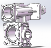
3.1:被加工零件的分析 7
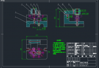
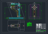
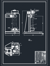
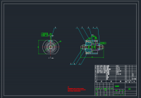
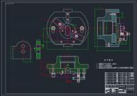
3.2:端盖钻孔夹具装配图分析 8
第四章、翻转式钻床夹具非标准零件的设计 11
4.1:平头支撑定的二维视图设计 11
4.2:定位销的二维视图设计 12
4.3:定心轴的二维视图设计 15
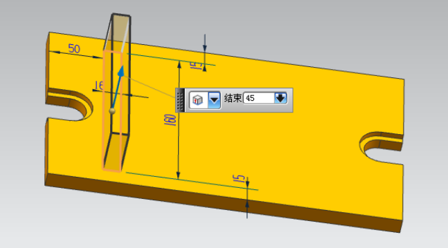
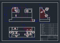
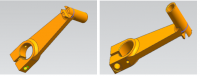
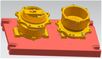
4.4:夹具体二维视图设计 15
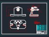
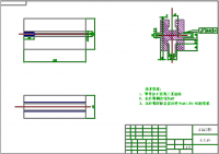
4.5:钻模板的二维视图设计 18
第五章、翻转式钻模夹具的三维设计 19
5.1标准零件的三维视图的绘制 19
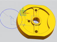
5.2:非标准零件的三维视图的绘制 21
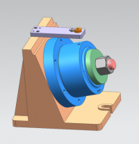
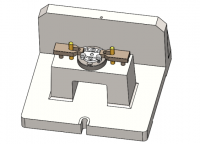
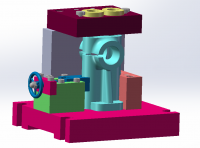
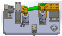
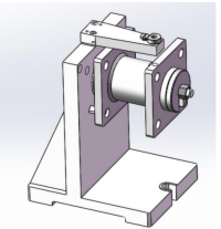
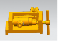
5.3:端盖钻孔夹具的三维装配图的设计 35
第六章、回顾总结 36
6.1课题成果 36
6.2存在问题 37
6.3收获体会 37
致谢 38
参考文献 39
附录 40
附录1:端盖钻孔夹具装配图 41
附录2:平头支承零件图 42
附录3:定位心轴零件图 43
附录4:夹具体零件图 44
附录5:钻模板零件图 45
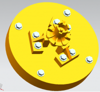
附录6:锁紧螺母三维造型效果图 46
附录7: 平头支承三维造型效果图 47
附录8:定位心轴三维造型效果图 48
附录9:定位销三维造型效果图 49
附录10:夹具体三维造型效果图 50
附录11:钻模板三维造型效果图 51
附录12:装配体三维造型效果图 52
附录13:装配体爆炸图三维造型效果图 53
参考文献
[1] 何铭新,钱可强. 机械制图[M].5版. 北京:高等教育出版社,2003
[2] 班纳吉. 虚拟制造. 清华大学出版社, 2005
[3] 胡家秀. 机械设计基础. 北京:机械工业出版社,2008
[4] 方晨. AUTOCAD 2007中文版实例教程. 上海科学普及出版社,2007
[5] 过小容,李坤. UG三维造型与数控加工编程实例精解. 辽宁科学技术出版社,2009
http://www.bysj1.com/ http://www.bysj1.com/html/5468.html
http://www.bysj1.com/html/5368.html