


等速万向节的成形工艺及模具设计
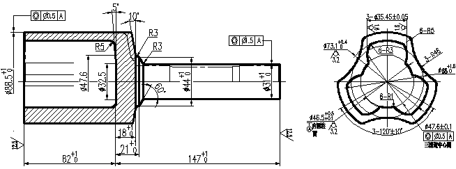
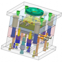
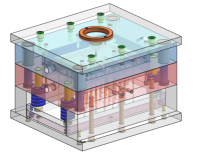
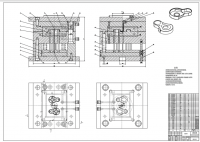
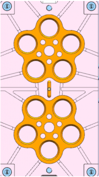
摘要: 主要研究TJ类型传动装置中的三柱槽壳的温锻工艺及模具的设计。先用UG建出三维的零件图,通过UG软件可以得知三维零件的体积等一些参数。根据零件的体积参数和要求设计出挤压毛坯的长度和直径。根据体积不变原则和工艺图的一些要求,用CAD设计出成形后每步工艺的工艺图。接着用UG建出简单的上下模具,并以STL的格式保存。运用软件进行模拟三个工艺过程,验证工艺图的合理性。根据模拟的情况修改每步工艺图。最后根据修改后的工艺图分别设计出每步工艺的上下模具。本文中模具的设计主要是根据查阅的书籍和一些工厂实际操作的经验值来设计的,并根据机床的装配重新完善模具参数。主要是对定位和支撑部分参数的修改,使模具可以与加工所使用的四柱液压机来配合。最后按照机床本身的尺寸要求和一些标准件的要求,可以设计出模具的装配图。
关键词:三柱槽壳 CAD DEFORM 有限元分析 模具设计
CVJ Forming Technology and Die Design
Abstract This paper studies forming technology and die design of three columns tank shell in TJ transmission. First to build three-dimensional parts with the UG, the volume of three-dimension can be learned by UG software.Design length and diameter according to the volume and so on. Design every artwork after the molding process with CAD. Then use UG to built the simple upper and lower dies and save them as STL. Using DEFORM software to simulate and finite element analysis, in order to verify the reasonableness of the process diagram. Modify each step of the process diagram according to situation simulated. Finally, design the upper and lower dies of each process step. Mold design is mainly based on books and experiences in factory. And re-perfect mold parameters according to the machine assembly, primarily to modify the positioning and support some parameters, so that the mold can match hydraulic machine. Finally, in accordance with the requirements and the size of the machine itself, we can design the mold assembly drawing,and complete the assembly FIG of design.
Key words three columns tank shell CAD DEFORM Finite Element Analysis
Mold Design
目 录
摘 要 1
第一章 引言 3
第二章 挤压概论 4
2.1 挤压的定义 4
2.2 挤压的特点 4
2.3 挤压的类型 4
2.3.1 按挤压方向分类 4
2.3.2 按挤压温度分类 5
2.4 小结 5
第三章 工艺方案及参数 5
3.1 下料 6
3.2 抛丸 6
3.3 石墨涂层 6
3.4 温锻感应中频加热 6
3.5 正挤压杆部 6
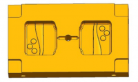
3.6 墩粗 8
3.7 反挤压 9
3.8 退火、磷化皂化处理 10
3.9 本章小结 10
第四章 DEFORM模拟与分析 10
4.1 DEFORM简介 10
4.2 正挤压模拟 11
4.2.1 创建新的项目 11
4.2.2 设置模拟控制初始条件 11
4.2.3 创建对象 12
4.2.4 定义驱动条件 14
4.2.5 设置模拟控制信息 15
4.2.6 设置对称 16
4.2.7 设置对象间关系 17
4.2.8 补偿体积 18
4.2.9 生成数据库 18
4.2.10 分析模拟 19
4.2.11 后处理 19
4.3 墩粗 20
4.3.1 创建对象 20
4.3.2 设置模拟控制信息 21
4.3.3 设置对象间关系 21
4.4 反挤压 22
4.5 修改工艺参数 23
4.5.1 模拟过程后尺寸的测量 24
4.5.2 工艺参数总图 24
4.6 本章小结 24
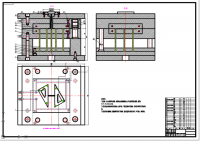
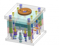
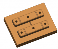
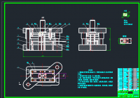
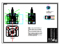
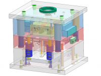
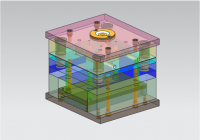
第五章 模具设计 26
5.1 模具概论 26
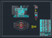
5.2 正挤压模具设计 26
5.3 墩粗模具设计 29
5.4 反挤压模具的设计 31
5.5 本章小结 34
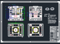
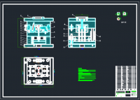
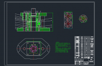
第六章 模具装配图 35
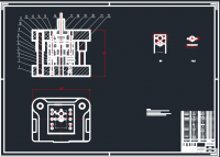
6.1 正挤压模具装配图 35
6.1.1 装配模具的特点及要求 35
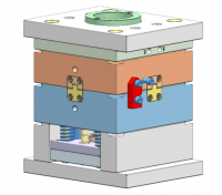
6.1.2 模具结构设计 35
6.1.3 模具的装配 36
6.1.4 模具的工作过程 36
6.2 墩粗模具装配图 36
6.3 反挤压模具装配图 37
6.4 本章小结 37
结 论 38
致 谢 38
参考文献 39
参考文献
[1] 中国锻压协会.汽车典型锻件生产[M].北京:国防工业出版社,2009.
[2] 张水忠.挤压工艺及模具设计[M].北京:化学工业出版社,2008.
[3] 贾俐俐.挤压工艺及模具[M].北京:机械工业出版社,2004.
[4] 翟德梅.挤压工艺及模具[M].北京:化学工业出版社,2004.
[5] 田福祥.挤压模和镦锻模75例设计应用评析[M].北京:机械工业出版社,2011.
[6] 张莉,李升军.DEFORM在金属塑性成型中的应用[M].北京:机械工业出版社,2009.
[7] 胡建军,李小平.DEFORM-3D塑性成形CAE应用教程[M].北京:北京大学出版社,2011.
[10] 王祖唐,关廷栋.金属塑性成形理论[M].北京:机械工业出版社,1989.
[11] 梁继才,黄良驹.星形套闭塞模锻光塑性模拟研究[J].机械强度,2003.
[12] 朱伟成.汽车零件精密锻造技术.北京:北京理工大学出版社,1999.
[13] 王学文,刘汉贵.挤压组合凹模的设计.北京:国防工业出版社,1998.
[14] Yeo H T, Choi Y, Hur K D. Analysis and design of the prestressed cold extrusion die [J]. International Journal of Advanced Manufacturing Technology,2001.
[15] Mok CK, Chin KS, Ho KLJ (2001) An interactive knowledge-based CAD system for mould design in injection moulding processes. Int J Adv Manuf Technol 17.
[16] Tang D, Eversheim W, Schuh G (2003) Concurrent metal stamping part and die development system. Proc Inst Mech Eng B J Eng Manuf 217.
http://www.bysj1.com/html/7966.html
http://www.bysj1.com/html/7956.html